Next: Kernel Module Implementation Overview Up: lfs Previous: User's Guide Contents
This chapter describes the on-disk structures we used in our implementation of a log-structured file system. Please note that we assume the reader is familiar with both traditional UNIX file system layout (that is explained for example in [3]) and general concepts of log structured filesystems as they are described in [1] and [2]. Please read through at least these two papers if you have not done so already. We have based our work particularly on the latter and won't go into much detail in cases when our implementation is almost the same.
All on-disk structures described in this section are defined in file include/lfs_fs.h. Please refer to it for exact definitions, comments and details.
Before we proceed to various structures present on the device, it essential to spend a number paragraphs with a few basic but fundamental design decisions and basic types. First and foremost, all multi-byte integers on the disk are stored in little-endian format. It is therefore necessary to use appropriate conversions whenever accessing any such integer that ever reaches the disk. Secondly, all structures we store on the disk are packed so that the compiler does not include any padding and thus they have the same binary representation on all platforms. This also means that the programmer is responsible for word alignment of individual items of these structures.
The current source code often requires that size of a particular structure must be a power of two. In this document we try to explicitly warn about these requirements whenever describing such a structure but it is necessary to double check before changing any on-disk structure whatsoever. Sometimes there are other requirements, for example two structures found in the ifile must have the same size. In other words, changing the on-disk structures is a delicate task that must be done thoughtfully.
Finally, this is an overview of the basic types specific to LFS that are used in on-disk structures:
We assume the reader is familiar with concepts of traditional file systems in UNIX environments (which are described for example in [3]) and therefore we will not describe those that LFS uses as well in much detail. However, let us at least briefly mention the most important ones.
Most file systems divide the underlying device into smallest
addressable and indivisible units called blocks and so do we. Even
though some of our metadata can share blocks (for example inodes can),
files in particular are always internally accessed with block
granularity. At this stage, our blocks are 4096 bytes long (see
limitations on page ![[*]](crossref.png) ).
).
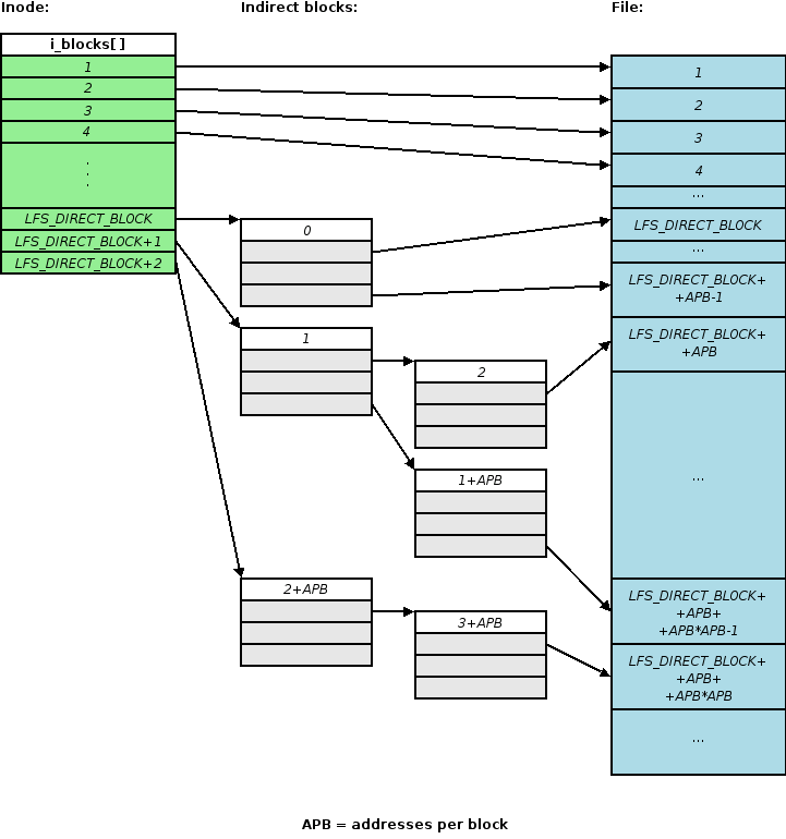
Most importantly, we also use the traditional indexing structure of UNIX file systems, namely the inode and indirect blocks. However, indirect blocks are numbered as described in the next section. LFS also has superblocks that represent data global to the file system and are the only structures that are not written in a log-like manner. The last common concept shared with traditional file systems is that directories are represented with files with a given internal format and special access methods.
Both indirect and data blocks are assigned an index that uniquely identifies them within an inode. The index of a data block is simply its offset in bytes divided by the block size. Indirect blocks are numbered in a pre-order depth first search manner. The figure 4.1 describes exactly how this is done.
All log structured file systems we know of statically partition the
disk into segments of the same and fixed
size. [4] discusses the impact of various segment sizes and
recommends
of the disk. Given today's
disks, the recommended value usually varies in between one and two
megabytes. In order to diminish the cleaning overhead and to limit the
number of possible configurations (see limitations on page
), the current version of LFS uses segments
one megabyte long.
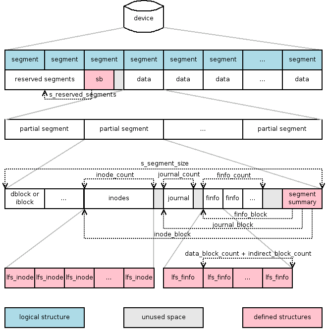
There are three main types of segments (see figure 4.2):
.
Every log structured file system needs a means of tracking state of individual segments and inodes. Whereas Sprite-LFS [1] used a special kernel table to store this information, BSD-LFS [2] moved both to an immutable file called ifile and we have adopted the same approach. Ifile in our implementation of LFS consists of two parts and its structure is depicted in the figure 4.3.
The first part of the ifile is called segment usage table. This table is created by mkfs and has a fixed size for the entire life of a particular file system instance. It contains an entry for each segment with information about how much live data and inodes the segment contains, what is its current logical sequential number or segment counter (see section 4.7) and flags to distinguish in between various types and states of segments. This part of ifile is especially important for the garbage collecting and segment allocating subsystems described by sections...
The second part of the ifile is an inode table. This table grows as inodes are created in the file system. Every inode is described by an item in this table which enables us to:
Obviously, since it is likely that the number of items in both segment usage table and inode table will be very large, it is important to keep their items small. Currently, both structures are 16 bytes long. The current code depends on the fact that both structures have the same size which is a power of two. This requirement greatly reduces complexity and must be observed when modifying ifile internals.
When accessing various parts of the ifile from kernel, the programmer should use the appropriate routines in ifile.c. A very brief summary of the four most important are given in table 4.1. Please refer to the source code and relevant comments for more information. As a side note, a new inode is created by lfs_ifile_new_ino() and they are deleted by lfs_ifile_free_ino().
Of course, it is essential that concurrent access to all parts of the ifile is avoided. This is done using page locks. Each item is simply protected by the page lock of the page it resides in. Functions listed in table 4.1 lock pages properly for you.
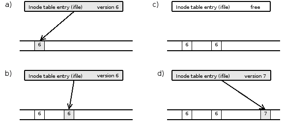
Since log structured file systems store all data in a single log, the data is never written to the same position from which it was read or which it was written to before. The same stands also for inodes, indirect blocks and even for the ifile (see section 4.5). Naturally, only the chronologically last copy of such data contains the currently valid version. Such inodes and blocks will be referred to as live. On the other hand, all other copies are outdated at any given moment. Such copies are referred to as dead and are subject to garbage collection.
In order to collect garbage safely, it is important to be able to determine whether a particular block or inode is alive or not. Strictly speaking, an inode on the disk is alive if and only if the corresponding item of the inode table points to it. Similarly a block is alive if and only if it is being pointed to by either the inode or an indirect block. In order to speed the process of finding out the live status of an entity, log structured file systems introduce so called inode versions. An inode version is a number that is associated with an inode number and that is incremented every time the inode is truncated to zero or the inode number is recycled and assigned to a newly created inode. When it is known that a block or an inode structure on the disk have an inode version different from the current one, they can be safely considered dead (see figure 4.4). Versions of inodes are used when collecting data and indirect blocks in the same way, the benefit of using them can actually be much bigger because loading the inode or even a few indirect blocks can be avoided.
 |
Log structured file systems need to finish a segment when they finish their part of the sync syscall. Both Sprite-LFS [1] and BSD-LFS [2] use so called partial segments in order not to waste space by leaving the rest of the segment unused. Our implementation closes partial segments at a few more occasions (fsync, pre-sync, flushing excessive amounts of journals and so on) in a very similar way.
Throughout this text, unless we explicitly specify we refer to a partial segment, we mean the whole, physical, one megabyte long one. For example, the inode usage table in ifile has exactly one item for each physical segment, even if it contains multiple partial segments.
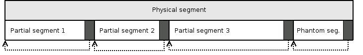
Every partial segment has a special structure called segment summary at the end. We will discuss particularities of partial segments and their summaries in the next chapter, at this point we only need to say that the summary contains the length of the partial segment. Moreover, the physical segment is always fully covered by partial segments, even if the last one is entirely empty. Such empty partial segment is called a phantom segment and is required to locate the previous partial segments. Thus, there is always a valid segment summary at the end of every physical segment (if it has ever been written to). Because every partial segment has its size recorded at a known place at the end and because we know the end of the last partial segment, all segment summaries are accessible and all partial segments identifiable. The figure 4.5 contains an example.
 |
Even though segments form a log, this does not continuously grow from the beginning of the device towards the end. As data are overwritten and garbage collected, any free segment can be the next one in the log. Therefore, the log is actually formed by a chronological or logical ordering of the segments. During a crash recovery, a roll forward utility must be able to follow the chain of segments in the order in which they were created by the file system module. Therefore, every segment summary contains the number of the segment that will be used next. Superblock contains the number of the next segment at the time of the end of a sync operation.
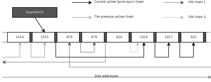
Needles to say, that is not enough. Only half-written segments cannot be recovered. Therefore, every partial segment summary contains a CRC of itself and of first 32 bytes of each sector that was written. Furthermore, if the next planned segment was not actually written to, an old segment could be mistaken for a new one. That is why every segment is assigned a global number that is incremented every time a new segment becomes active (i.e. the one being written to). This number is called the segment counter. Again, the superblock contains the counter of the next segment at the time of the last sync and every segment summary contains the counter of the next segment too. This leads to segments chained in a way similar to the figure 4.6. Moreover, the segment counter is the most important means of specifying time of various events in LFS. For example, it is necessary to know what the counter was when the last sync took place or a snapshot was mounted.
 |
Partial segments contain data blocks, indirect blocks, inodes, journal lines, finfo structures and, as we already know, a segment summary. The figure 4.7 shows how these parts are ordered and located whereas the Figure 4.8 presents you the definition of segment summary. Please note that journal_block, inodes_block and finfos_block are addresses in blocks.
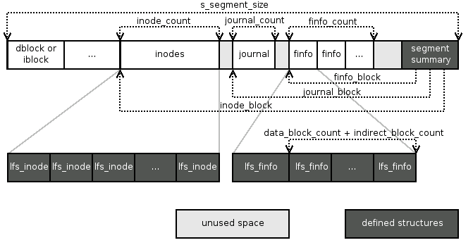 |
If there are any indirect or data blocks present in a partial segment, they are placed one after another right from the beginning. As we have already stated in the previous section, the beginning of a partial segment can be determined by subtracting the partial segment size from the address of the end of the segment summary. Number of these blocks can be determined from finfos (see below).
Inodes, if present, immediately follow the blocks. Currently one on-disk inode has size of 256 bytes, which means there are 16 inodes per one block. The address of the first block containing the inodes can be obtained from the inodes_block field of the segment summary which also contains the number of inodes stored in this segment in inodes_count. If this number is not divisible by 16, the rest of the last block is unused and cleared. Therefore one can traverse the inodes not by their count but until a structure filled with zeros is reached (as segment building code does).
Again, it is important to bear in mind that the size of the on-disk inode is a power of two. The current code depends on it and not observing this principle would break segment building.
The purpose of journal blocks is to inform the roll-forward utility about directory operations4.1 These blocks contain so called jline structures that can span block and even segment boundaries but not across a sync. Each one describes an individual directory operation and its format differs according to the operation's type (see section 5.11.8 for details). The most important rule is that a jline describing a particular operation are saved no later than in the same partial segment that contains any part of the affected inodes. On the other hand, it can be stored to disk substantially earlier because jlines are never reordered and so they reach the disk exactly in the order in which they were carried out by the operating system.
When there are journal blocks in the partial segment, journal_count contains the number of blocks they span across and journal_block points to the first such block. The end of jlines is determined by reaching a cleared jline structure.
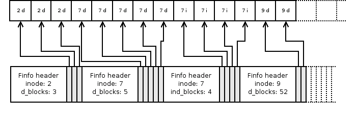
When cleaning a segment, the garbage collector must be able to determine what individual blocks in a segment contain. That means to which inode they belong, whether they hold data or are indirect blocks and what is their index (as described in the section 4.3. This is accomplished using so called finfo structures. Take a look at its definition in the figure 4.9. It is a variable length structure consists of a header identifying the inode and a number of 64-bit unsigned integers containing indices. The field indirect_block_count tells how many indices of indirect blocks follow the header while data_block_count determines the number of offsets of direct blocks in the finfo. At the moment, only one of these numbers can be non-zero. version contains the version and ino the number of the inode the blocks belong to.
Finfos also have size constraints. The Size of struct lfs_finfo must be divisible by the size of lfs_finfo_block_t which itself must be a power of two.
The finfo blocks correspond to the indirect and data blocks at the beginning of the partial segment. First index in first finfo identifies the first block in the partial segment, the second one refers to the second block and so on. After there are no indices left in the first finfo, the second one is used etc. See figure 4.10.
 |
Viliam Holub 2006-12-04